Python基于欧拉角绘制一个立方体
微小冷 人气:0先画个立方体
工欲善其事、必先利其器,在开始学习欧拉角模拟之前,可先绘制一个立方体。
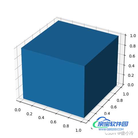
在matplotlib中,这个任务可通过plt.voxels实现,下面先绘制一个最质朴的立方体

代码为
import matplotlib.pyplot as plt
import numpy as np

x, y, z = np.indices((2, 2, 2))
filled = np.ones((1,1,1))
ax = plt.subplot(projection='3d')
ax.voxels(x,y,z, filled=filled)
plt.show()
其中,x,y,z表示顶点,filled表示被填充的区域。由于其顶点数量为2×2×2,故只有一个立方体,从而filled是一个1×1×1的张量。
有了立方体之后,就可以进行欧拉角仿真了。
欧拉角和旋转矩阵
为了尽快进入演示部分,故对原理的介绍从略,仅从二维平面上的旋转矩阵出发,做一个简单的推导,而三维旋转矩阵,至少在形式上与二维是雷同的。
假设坐标系中有一个向量(x,y),其模长为r=√x2+y2,角度为θ0=arctan(y/x).若将其围绕坐标原点逆时针旋转θ,则其坐标变为

由于x=rcosθ0, y=rsinθ0,则上式可以写为

写成矩阵形式即为

也就是说,在平面直角坐标系上,向量绕原点顺时针旋转θ,相当于左乘一个旋转矩阵。
推广到三维,为了限制xy坐标平面上的旋转,要将其旋转中心从原点扩展为绕着z轴旋转,从而三维旋转矩阵可推广为

同理可得到绕三个轴转动的旋转矩阵,为了书写方便,记Sθ=sinθ,Cθ=cosθ,可列出下表。

初步演示
将旋转矩阵写成函数是十分方便的,下面用lambda表达式来实现
import numpy as np
# 将角度转弧度后再求余弦
cos = lambda th : np.cos(np.deg2rad(th))
sin = lambda th : np.sin(np.deg2rad(th))

# 即 Rx(th) => Matrix
Rx = lambda th : np.array([
    [1, 0,       0],
    [0, cos(th), -sin(th)],
    [0, sin(th), cos(th)]])
Ry = lambda th : np.array([
    [cos(th),  0, sin(th)],
    [0      ,  1, 0],
    [-sin(th), 0, cos(th)]
])
Rz = lambda th : np.array([
    [cos(th) , sin(th), 0],
    [-sin(th), cos(th), 0],
    [0       , 0,       1]])
有了旋转矩阵,就可以旋转,接下来让正方体沿着三个轴分别旋转30°,其效果如下

由于ax.voxels在绘图时,要求输入的是拥有三个维度的数组,而旋转矩阵是3 × 3 3\times33×3矩阵,相当于是二维数组,彼此之间可能很难计算,所以实际计算时,需要对数组维度进行调整
import matplotlib.pyplot as plt
# 用于批量调节x,y,z的数组维度
Reshape = lambda x,y,z : [x.reshape(2,2,2), y.reshape(2,2,2), z.reshape(2,2,2)]


filled = np.ones((1,1,1))
x, y, z = np.indices((2, 2, 2))
# 将x,y,z展开,以便于矩阵计算
xyz = np.array([x,y,z]).reshape(3,-1)

fig = plt.figure("rotate")
# 此为未旋转的正方体
ax = fig.add_subplot(1,4,1, projection='3d')
ax.voxels(x,y,z, filled=filled)

# 绕x轴旋转30°
X, Y, Z = Rx(30) @ xyz
ax = fig.add_subplot(1,4,2, projection='3d')
ax.voxels(*Reshape(X, Y, Z), filled=filled)

# 绕y轴旋转30°
X, Y, Z = Ry(30) @ xyz
ax = fig.add_subplot(1,4,3, projection='3d')
ax.voxels(*Reshape(X, Y, Z), filled=filled)

# 绕z轴旋转30°
X, Y, Z = Rz(30) @ xyz
ax = fig.add_subplot(1,4,4, projection='3d')
ax.voxels(*Reshape(X, Y, Z), filled=filled)

plt.show()
不同转动顺序的影响
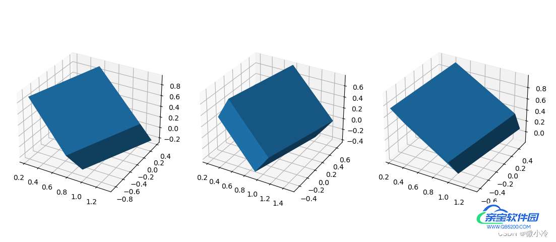
众所周知,矩阵计算是不能交换的,反映到实际生活中,就是不同的旋转次序,可能会导致完全不同的结果,接下来沿着不同的旋转次序,来对正方体进行旋转,效果如下

需要注意的是,由于矩阵左乘向量表示对向量进行旋转,所以距离向量最近的矩阵表示最先进行的操作,即RzRyRxr ⃗ 表示先转Rx ,Ry次之,Rz最后。
代码如下
filled = np.ones((1,1,1))
x, y, z = np.indices((2, 2, 2))
xyz = np.array([x,y,z]).reshape(3,-1)

fig = plt.figure("rotate")
# 旋转顺序 x, y, z
X, Y, Z = Rz(30) @ Ry(30) @ Rx(30) @ xyz
ax = fig.add_subplot(1,3,1, projection='3d')
ax.voxels(*Reshape(X, Y, Z), filled=filled)

# 旋转顺序 z, y, x
X, Y, Z = Rx(30) @ Ry(30) @ Rz(30) @ xyz
ax = fig.add_subplot(1,3,2, projection='3d')
ax.voxels(*Reshape(X, Y, Z), filled=filled)

# 旋转顺序 y, x, z
X, Y, Z = Rz(30) @ Rx(30) @ Ry(30) @ xyz
ax = fig.add_subplot(1,3,3, projection='3d')
ax.voxels(*Reshape(X, Y, Z), filled=filled)

plt.show()
总之,虽然分不清谁是谁,但最起码可以看清楚,不同的旋转顺序的确导致了不同的旋转结果。
旋转演示
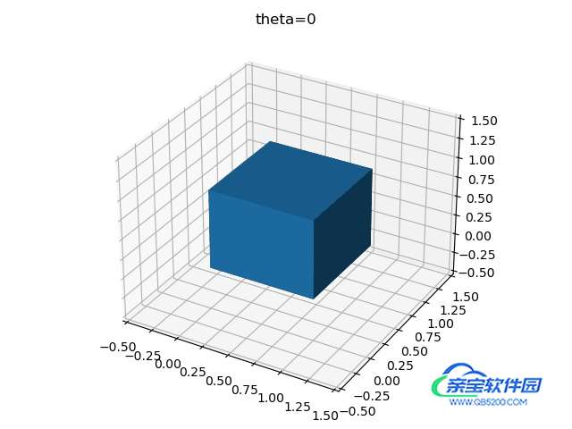
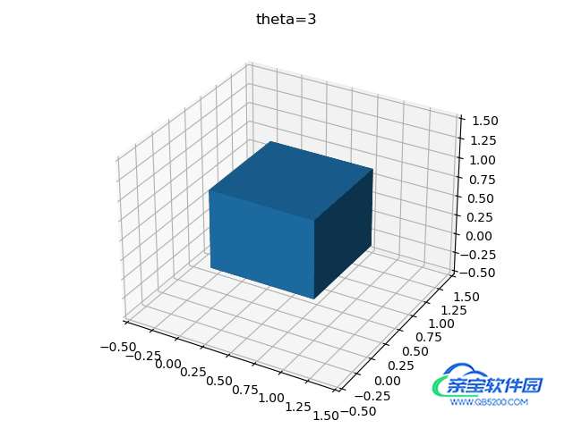
为了更加清楚地表示这一过程,可以将正方体的旋转过程绘制下来,先考虑单轴旋转,假设每次旋转3°,绕X轴旋转30次,则可得到

import numpy as np
import matplotlib.pyplot as plt
from matplotlib import cm
import imageio

filled = np.ones((1,1,1))
x, y, z = np.indices((2, 2, 2))
xyz = np.array([x,y,z]).reshape(3,-1)

def saveGif(X,Y,Z, gifs):
    plt.cla()
    ax = plt.subplot(projection='3d')
    ax.voxels(*Reshape(X, Y, Z), filled=filled)
    ax.set_xlim(-0.5,1.5)
    ax.set_ylim(-0.5,1.5)
    ax.set_zlim(-0.5,1.5)
    ax.set_title(f"theta={th}")
    plt.tight_layout()
    plt.savefig(f"tmp.jpg")
    gifs.append(imageio.imread(f"tmp.jpg"))

gifImgs = []
th = 0

for i in range(30):
    X,Y,Z = Rx(th)@xyz
    th += 3
    saveGif(X, Y, Z, gifImgs)

imageio.mimsave("test.gif",gifImgs,fps=10)
通过这个方法,可以将不同顺序的旋转矩阵可视化表示,
filled = np.ones((1,1,1))
x, y, z = np.indices((2, 2, 2))
xyz = np.array([x,y,z]).reshape(3,-1)

gifImgs = []
th = 0
for _ in range(10):
    X,Y,Z = Rz(0) @ Rx(0) @ Ry(th) @ xyz
    th += 3
    saveGif(X, Y, Z, gifImgs)

th = 0
for i in range(10):
    X,Y,Z = Rz(0) @ Rx(th) @ Ry(30) @ xyz
    th += 3
    saveGif(X, Y, Z, gifImgs)

th = 0
for i in range(10):
    X,Y,Z = Rz(th) @ Rx(30) @ Ry(30) @ xyz
    th += 3
    saveGif(X, Y, Z, gifImgs)

imageio.mimsave("test.gif",gifImgs,fps=10)
最后得到三种不同旋转顺序的区别
x-y-z

z-y-x

y-x-z

加载全部内容
 爱之家商城
爱之家商城 氢松练
氢松练 Face甜美相机
 花汇通
花汇通 走路宝正式版
 天天运动有宝
 深圳plus
 热门免费小说