03 串口发送端口Rs232之简单驱动1
执著的耗子 人气:0前言:
最近想实际做两个项目,认真学习怎么做一个系统,所以在看FPGA小梅哥2019的培训课程,发现他是从各个模块讲起,就是没有直接讲一个整体的系统,而是从一些模块开始,如串口发送。刚开始我想直接创造自己代码,但我觉得既然我是跟着别人学项目,那首先应该按照别人的要求,一步步来,学习别人的思路。模仿。
小梅哥先讲的是,串口发送模块,这个和他初级阶段的发送模块是相同的(经验就是把一些写好的模块,可以用在以后的实际工程,反复利用。启示就是,对于每一个基本模块,不要求能创造自己设计思路,但一定得熟练掌握别人的,可以灵活应用修改,比如黑金的串口通信模块,就特别好用。)
一 设计定义
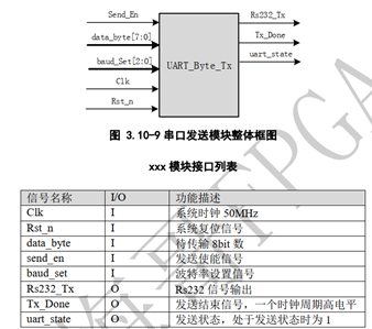
第一系统功能:串口发送,即实现能够让串口发送八位数据位,并仿真通过。
简单概括为两个部分:一是串口发送的波特率设置。二是八位数据位的发送。
第二遇到问题及解决;
解决问题:抓因果关系。如下面的两个问题:
A: bps_cnt_q一直在第零位。(由于设计逻辑是波特率时钟一为零,则bps_cnt_q赋值为零。修改为保持就解决勒)
B: 小梅哥仿真设计中,只让Send_en保持一个时钟周期,发送时间不够,怎么等到了发送完成信号的高电平。(原因是只要让Send_en为高电平,然后uart_state就会一直保持这个高电平,直到发送完成)即控制发送实际上是uart_state。(类似下面的代码,flag 相当于uart_state)
|
if(send_en) flag <= 1else if(send_over)flag <= 0; |
启示是:对信号的控制方式有两种:一是通过边沿触发(如按键按下,为下降沿触发)。二是电平的状态(或者状态机)。如串口发送是靠uart_state的高电平状态,控制发送。
C: 为啥小梅哥,设计的代码是从分频计数值为1时,就让波特率时钟为高电平。(为了避免延迟一个数据位的时间(即多等待一个数据位的发送时间),从计数值一开始,可以提升电路效率。)
|
|
第三 串口发送的原理
|
第一部分:串口发送模块框图
对第一个问题记录,先是通过仿真波形发现输出显示不正确,再加入发送模块的波形,看到bps_cnt_q一直为0. 修改为红色部分代码: always@(posedge clk or negedge rst_n) if(!rst_n) bps_cnt_q<=4'd0; else if(bps_cnt_q==4'd12) bps_cnt_q=4'd0; else if(bps_clk) bps_cnt_q<=bps_cnt_q+1'b1; else bps_cnt_q<=bps_cnt_q; 解决办法的问题:抓因果关系。即刚开始看Rs232_tx波形一直为高电平,那就在模块中看到Rs232_tx与bps_cnt_q 有关,那就看看bps_cnt_q是否一直处于初始状态,即0(因为这时Rs232_tx为高).观察bps_cnt_q 的波形果然一直处于零,那就再看看关于bps_cnt_q的代码,发现只要波特率时钟bps_clk为低电平,则让bps_cnt_q为零。找到这个问题,解决办法:那直接在bps_clk为低电平时,则让bps_cnt_q保持为前一个状态,就会每来一个波特率时钟,bps_cnt_q一直加到11.
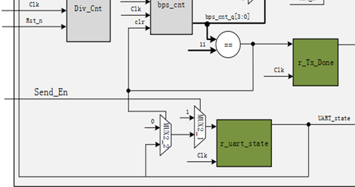
第二部分:串口发送模块原理图(电路图)
波特率查找表
|
||||||||||||||||||||
二 设计输入
简单总结:照图施工。根据上面设计定义的模块框图和电路结构图,从上到下,从输入到输出,按因果或输入输出的先后逻辑编写好每一个模块就行了。
由串口发送模块结构图可知,有五种波特率选择器的查找表,还有波特率分频器,多路选择器,寄存器,二选一选择器等模块。由于篇幅有限,我就重点写发送控制信号,控制状态信号uart_state的设计。
电路结构图:
|
|
设计过程:
|
从第二个模块往右看(好好分析),发现为多路选择器,但发现它的输入不仅有r_data_byte,还有bps_cnt_q,那我继续看bps_cnt_q的输入bps_cn,而bps_cnt_q的输入为Div_cnt(分频计数器),分频计数器的输入除了bps_dr还有en_cnt, 而en_cnt就是uart_state(因为它们用线连起来的)而uart_state的输入是两级的二选一选择器, 结论:初级的二选一输入为bps_cnt_q为11时,则让初级的二选一输出uart_state为0.次级的二选一的输入为send_en, 当send_en,为高电平时则让次级的二选一输出uart_state为1.
|
核心模块:数据发送模块,则是根据时序图,即每隔一个波特率时钟,数据被移入一位,而数据的起始位引脚Rs232_tx为低电平,其他时刻(如停止位)为高,来判断起始位的到来,之后再一位位的送人数据位(从低到高串行)。
设计思路:线性序列就或多路选择器
代码如下
|
localparam START_BIT = 1'b0; localparam STOP_BIT = 1'b1; /https://img.qb5200.com/download-x/data transend reg tx_done; reg r_Rs_232; always@(posedge clk or negedge rst_n) if(!rst_n)beginr_Rs_232<=1'b1; tx_done<=1'b0; end else begin case (bps_cnt_q) 0:begin tx_done<=1'b0;r_Rs_232<=1'b1;end 1:begin r_Rs_232<=START_BIT;end 2:begin r_Rs_232<=r_data_byte[0];end 3:begin r_Rs_232<=r_data_byte[1];end 4:begin r_Rs_232<=r_data_byte[2];end 5:begin r_Rs_232<=r_data_byte[3];end 6:begin r_Rs_232<=r_data_byte[4];end 7:begin r_Rs_232<=r_data_byte[5];end 8:begin r_Rs_232<=r_data_byte[6];end 9:begin r_Rs_232<=r_data_byte[7];end 10:begin tx_done<=1'b0;r_Rs_232<=STOP_BIT;end 11:begin tx_done<=1'b1;end default: r_Rs_232<=1'b1; endcase end
|
注意点:我把tx_done直接写在了数据发送模块,在11时直接赋值为高,少写了tx_done的寄存器模块。
|
代码综合后的错误
|
附上完整设计代码:
|
module uart_tx ( send_en, data_byte, baud_set, clk, rst_n,
Rs232_tx, tx_done, uart_state
); input send_en; input [7:0]data_byte; input [2:0]baud_set; input clk; input rst_n;
output reg Rs232_tx; output tx_done; output uart_state;
reg [3:0]bps_cnt_q; reg uart_state; always@(posedge clk or negedge rst_n) if(!rst_n) uart_state <= 1'b0; else if(send_en) uart_state <= 1'b1; else if(bps_cnt_q == 4'd12) uart_state <= 1'b0;
else uart_state <= uart_state;
//multiplexer(多路选择器) reg [15:0]bps_dr; always@(posedge clk or negedge rst_n) if(!rst_n) bps_dr<=16'd0; else begin case(baud_set) 0:bps_dr<=16'd5207; 1:bps_dr<=16'd2603; 2:bps_dr<=16'd1301; 3:bps_dr<=16'd867; 4:bps_dr<=16'd433; default: bps_dr<=16'd5207; endcase end
/https://img.qb5200.com/download-x/data reg to store input data reg [7:0]r_data_byte; always@(posedge clk or negedge rst_n) if(!rst_n) r_data_byte<=8'd0; else if(send_en) r_data_byte<=data_byte; else r_data_byte<=r_data_byte;
/https://img.qb5200.com/download-x/div_cnt counter("分频") reg [15:0]div_cnt; always@(posedge clk or negedge rst_n) if(!rst_n) div_cnt<=16'd0; else if(uart_state) begin if(div_cnt==bps_dr) div_cnt<=16'd0; else div_cnt<=div_cnt+1'b1;
end else div_cnt<=16'd0;
//bps_clk gene reg bps_clk; always@(posedge clk or negedge rst_n) if(!rst_n) bps_clk<=1'b0; else if(div_cnt==16'd1) bps_clk<=1'b1; else bps_clk<=1'b0;
always@(posedge clk or negedge rst_n) if(!rst_n) bps_cnt_q<=4'd0; else if(bps_cnt_q==4'd12) bps_cnt_q=4'd0; else if(bps_clk) bps_cnt_q<=bps_cnt_q+1'b1; else bps_cnt_q<=bps_cnt_q;
localparam START_BIT = 1'b0; localparam STOP_BIT = 1'b1; /https://img.qb5200.com/download-x/data transend reg tx_done;
always@(posedge clk or negedge rst_n) if(!rst_n)begin Rs232_tx<=1'b1; tx_done<=1'b0; end else begin case (bps_cnt_q) 4'd0:begin tx_done<=1'b0;Rs232_tx<=1'b1;end 4'd1:begin Rs232_tx<=START_BIT;end 4'd2:begin Rs232_tx<=r_data_byte[0];end 4'd3:begin Rs232_tx<=r_data_byte[1];end 4'd4:begin Rs232_tx<=r_data_byte[2];end 4'd5:begin Rs232_tx<=r_data_byte[3];end 4'd6:begin Rs232_tx<=r_data_byte[4];end 4'd7:begin Rs232_tx<=r_data_byte[5];end 4'd8:begin Rs232_tx<=r_data_byte[6];end 4'd9:begin Rs232_tx<=r_data_byte[7];end 4'd10:begin tx_done<=1'b0;Rs232_tx<=STOP_BIT;end 4'd11:begin tx_done<=1'b1;end default: Rs232_tx<=1'b1; endcase end endmodule |
第三 仿真设计
|
`timescale 1ns/1ns `define clock_period 20 module uart_tx_tb; reg send_en; reg [7:0]data; reg [2:0]baud_set; reg Clk; reg Rst_n;
wire Rs232_tx; wire tx_done; wire uart_state; uart_tx uart_tx_m0 ( .send_en(send_en), .data_byte(data), .baud_set(baud_set), .clk(Clk), .rst_n(Rst_n),
.Rs232_tx(Rs232_tx), .tx_done(tx_done), .uart_state(uart_state)
);
initial Clk = 1; always#(`clock_period/2) Clk =~Clk;
initial begin Rst_n = 0; send_en = 0; data = 0;baud_set = 0; #(`clock_period*440+1); Rst_n = 1; #(`clock_period*440+1); baud_set = 4; #(`clock_period*440+1); data = {3'b110,3'b010,2'b11}; #(`clock_period*440+1); send_en =1; #(`clock_period); send_en =0; @(posedge tx_done) #(`clock_period*999+1); Rst_n = 0; #(`clock_period*666+1); $stop; end endmodule 仿真波形
|
通过这个串口发送设计,我明白了一是怎么照图施工(根据电路结构图设计代码)。二是怎么通过观察波形找到问题,抓因果关系,再修改对应的逻辑。三是设计好后,记得检查常见的三类错误。
加载全部内容


